

Even a small, low-cost IoT device can run edge computing, learn your hydration patterns, and sync seamlessly across devices.
I designed the PCB, sensor stack, and FreeRTOS-based firmware, and built a cloud backend to power SmartCoaster.
Continuously samples the HX711, filters for a stable baseline, detects “cup removed / replaced” events, computes the amount of water consumed, and queues a structured packet for upload.
Monitors global state set by the sensor & load-cell logic; when a countdown expires (or certain conditions are met) it toggles the buzzer pin & LED for short audible reminders.

Loadcell Task

Buzzer & LED
Task
Architecture Overview

Software: RTOS, Edge & Cloud
Explore some of RTOS Tasks in SmartCoaster:
FreeRTOS is a lightweight, open-source RTOS for microcontrollers that provides a preemptive scheduler plus queues, timers, and synchronization primitives to orchestrate concurrent tasks with deterministic timing.
FreeRTOS gives simple task-based concurrency to juggle sensors, networking, and UI on microcontrollers.


Timer, idle, and daemon tasks run automatically and provide timeouts, low-priority housekeeping, and deferred initialisation.
Polls the AHT20 every cycle, converts raw bytes into temperature and relative-humidity readings, and places the results onto a queue for the cloud task.
Brings up the network, maintains the MQTT session, publishes JSON packets for humidity and water-intake data, listens for control topics, and can trigger OTA firmware downloads when requested.
Runs an interactive UART shell: registers built-in commands, waits for user input in serial, executes handlers, and echoes results back to the terminal.
On update reset it mounts the SD, flashes the flagged image page-by-page to the app region, verifies CRC-32, and boots; on CRC failure it boots the golden image for safe recovery.
The Bootloader
FreeRTOS Services
Sensor Task
Wi-Fi & Cloud Task
CLI Task
Inspecting hardware integrity
I first performed a visual inspection, confirming all SMT components on the three PCBs were present with no obvious soldering issues. Next I tested the power section—including startup behavior, steady-state output, ripple, and load performance.
I verified peripherals such as the LED, button, I²C/UART communications, and SD-card firmware download. The integrity of all communication protocols was verified using a logic analyzer.


Task timing, context switches, and semaphore behavior were checked in Percepio Tracealyzer to confirm the task logic behaves as intended.

Hardware: the PCBA
ECAD layout
3D rendering
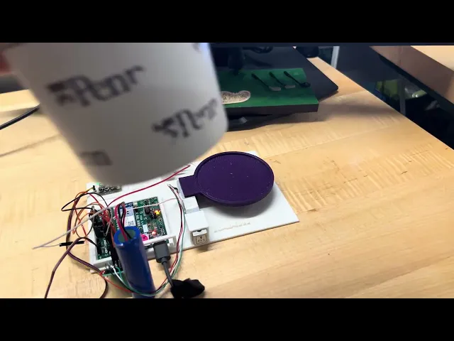
Assembly


Serial to USB
Provides the USB connection used for firmware download and runtime logging/terminal over UART/bootloader. The same USB port feeds VBUS to the BatteryCharger. Data (D+/D−) and power are broken out to test points for bring-up and measurement.
Memory
Hosts the memory that provides space for firmware updates. It includes a microSD socket and the associated read/write circuitry.
Two physical buttons (SW1, SW2) and one LED indicator handle mode selection, reset/confirm, and status display. Also includes connectors for the load cell and buzzer: the load cell feeds a through-hole amplifier (only non-SMT part) into the MCU ADC; the buzzer is driven by an MCU-controlled low-side MOSFET.
Boost Converter
Boosts the battery voltage to a regulated 5 V rail for peripherals that require it.
MCU Essentials
The controller is a SAMD21 inside the SAMW25 SoC. A WINC1500 Wi-Fi module connects over SPI. The MCU runs application logic, reads the AHT20 over I²C, samples the load-cell amplifier via ADC, and drives a low-side MOSFET for the buzzer as well as the on-board buttons and LED.
Buck Converter
Steps the battery voltage down to a regulated 3.3 V rail that powers the MCU, AHT20, the load-cell amplifier/logic, and the microSD. The stage includes the buck controller, inductor, and input/output capacitors, and its high-current loop is routed tightly to minimize ripple and EMI.
Power Management
Takes 5 V from USB to charge the single-cell Li-ion battery. The circuit includes charge-status indication, an NTC for thermal protection, charge-current-setting components, and battery-protection circuitry. USB VBUS is also routed into the system so the board can operate while charging.
Connectors
Two 3.3 V I²C ports—STEMMA QT and Qwiic with on-board pull-ups.
Top_Level
SmartCoaster
An IoT device for better hydration habits
